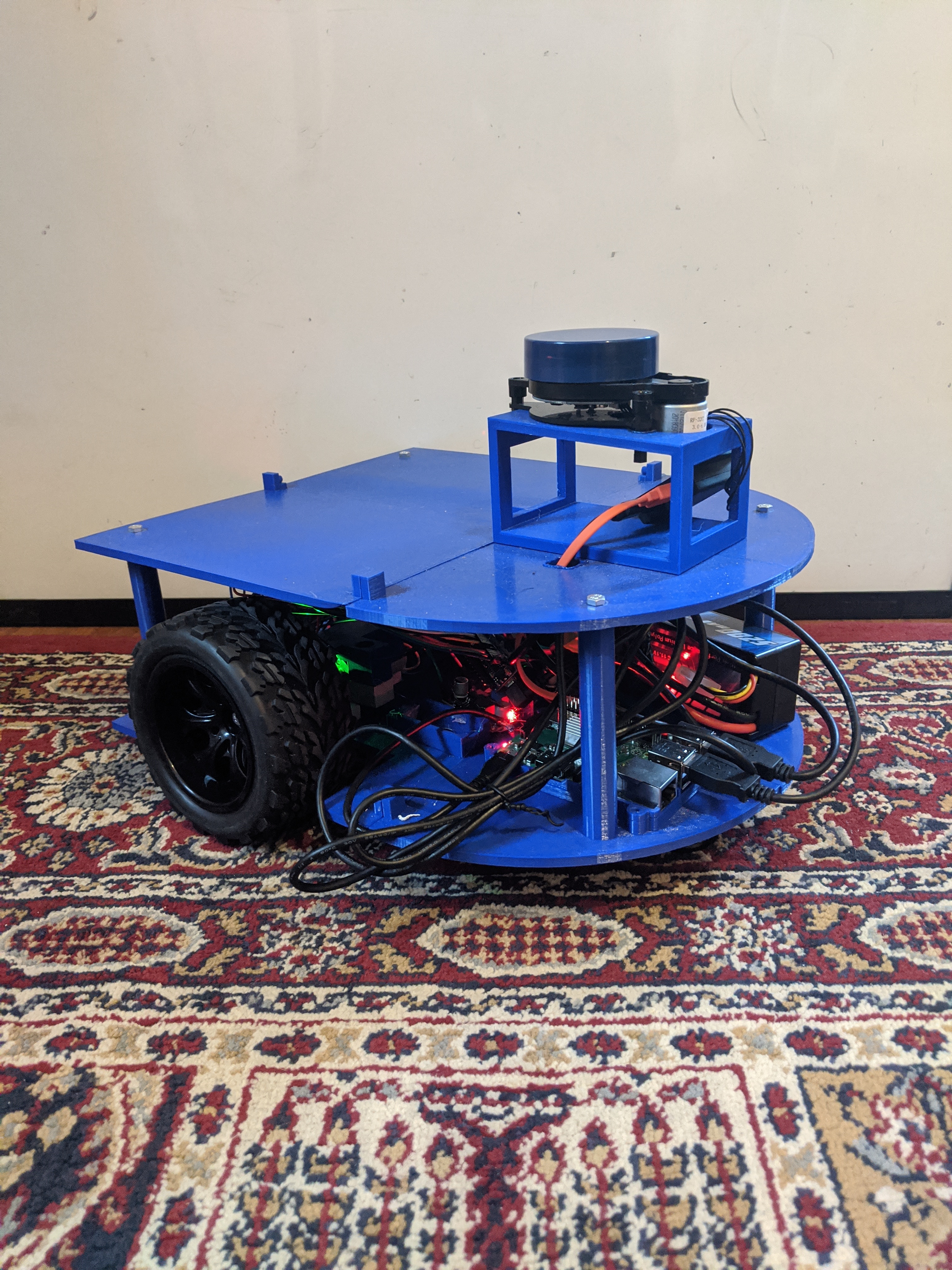
RoomE was a capstone project on my Computer Science degree. It was a robot built from the ground up which
would map an area using lidar. I created a mojority of the programatic logic of the system namely
the pathfinding algorithm, the frontier exploration algorithm, the interpretation of lidar data,
communicating via USB to the drive train system, and creating testing infrastructure for the system.
The project was a great challenge and included many opportunities to solve algorithmic problems along with
practical issues that occurred when constructing the physical product together.
RoomE had 5 different software components:
To give an overview of each, the lidar interface got data from the lidar and converted it into a form usable by the RoomE Map. The RoomE Map stored the overall map as a grid, held the orientation information of the RoomE, and could be updated by new scans in new locations using Continuous Iterative Closest Point (CICP) to correct for mistakes in the scans or the orientation updates. The RoomE Navigation component used the RoomE Map to find new areas to explore called frontiers, and provided a set of points that the RoomE would take to get to the new location. The Drive Train Calculations component was responsible for taking the points produced by the navigation and formatting them so that the drive train could understand them, and was also responsible for translating the odometry information from the drive train into orientation update information that could be used by the RoomE Map component. The Serial Communication component worked as a two way interface for communications between the drive train and the Drive Train calcualtions component. I was responsible for creating all of the software components except for the Drive Train Calculations component.
The flow of the program was to scan, update the map, find a new navigation target, navigate to that area, calculate an approximate new location coordinate, and repeat until there were no more frontiers to explore. The final map would then be saved.
The Lidar Interface is very simplistic, it only takes the output from the lidar module and converts it into a data type which can be interpreted by the RoomE Map. The only caveat is that the degree 0 was shifted by an integer that was discovered via experimentation. I believe this was a manufacturing defect. The lidar only gave an array of values denoting how far away each ray was, and the degree that the ray was shot from was denoted by the index in the array, I found that the degree 0 was not the 0'th element of the array, and found a shift was necessary to find the true zero degree.
The RoomE Map used an occupancy grid map, where each of the points on the grids were either occupied, unoccupied or unknown, it was a fuzzy representation such that 0 was definitely occupied, 1 was definitely unoccupied, and then anything inbetween was an estimate at certainty, with 0.5 as completely unknown.
The RoomE Navigation component takes the occupancy grid map, and uses breadth first search to walk through the grid through the unoccupied squares. It finds all of the frontiers which are locations which are borders of unoccupied and unknown areas. The entire set of unknown points which are neighbors with eachother and a known unoccupied point are considered a single frontier. For instance if RoomE made a scan in a hallway, it would see a frontier for each open door which it cannot see into.
The Serial Communication component is very simple and sends and recieves commands in an agreed upon format with the Arduino running the drive train. The drive train can only understand time to move the right and left wheel so it depends on the Drive Train Calculations component to transform the navigation points into wheel rotations. The Arduino then sends back the number of rotations of each wheel which can be used to calculate the new position more accurately which can then be used by the map system to adjust for any error.
| Message: |
|---|